Operating System Driver Provider Driver Version; Download Driver: Windows 2000 (32 bit) SCANLAB AG: 1.2.1.0 Download Driver: Windows XP (32 bit). To get to the dialog, choose Menu bar → Settings → System → Card → Advanced → Driver Settings for RTC3, RTC4, RTC5 or RTC6. Enable Marking On The Fly and then go to Settings. Figure 296: MOTF Settings for RTC Cards. Encoder Kx/Ky: Distance in x/y direction per encoder count. Example of a RTC MOTF-Kx/Ky calculation. Tech support scams are an industry-wide issue where scammers trick you into paying for unnecessary technical support services. You can help protect yourself from scammers by verifying that the contact is a Microsoft Agent or Microsoft Employee and that the phone number is an official Microsoft global customer service number.
Here, the individual options for RTC cards (RTC3, RTC4, RTC5 and RTC6) are described. Make sure that the hardware license for the RTC card (from Scanlab) includes Marking on the Fly.
For RTC cards, the following MOTF channels are available:
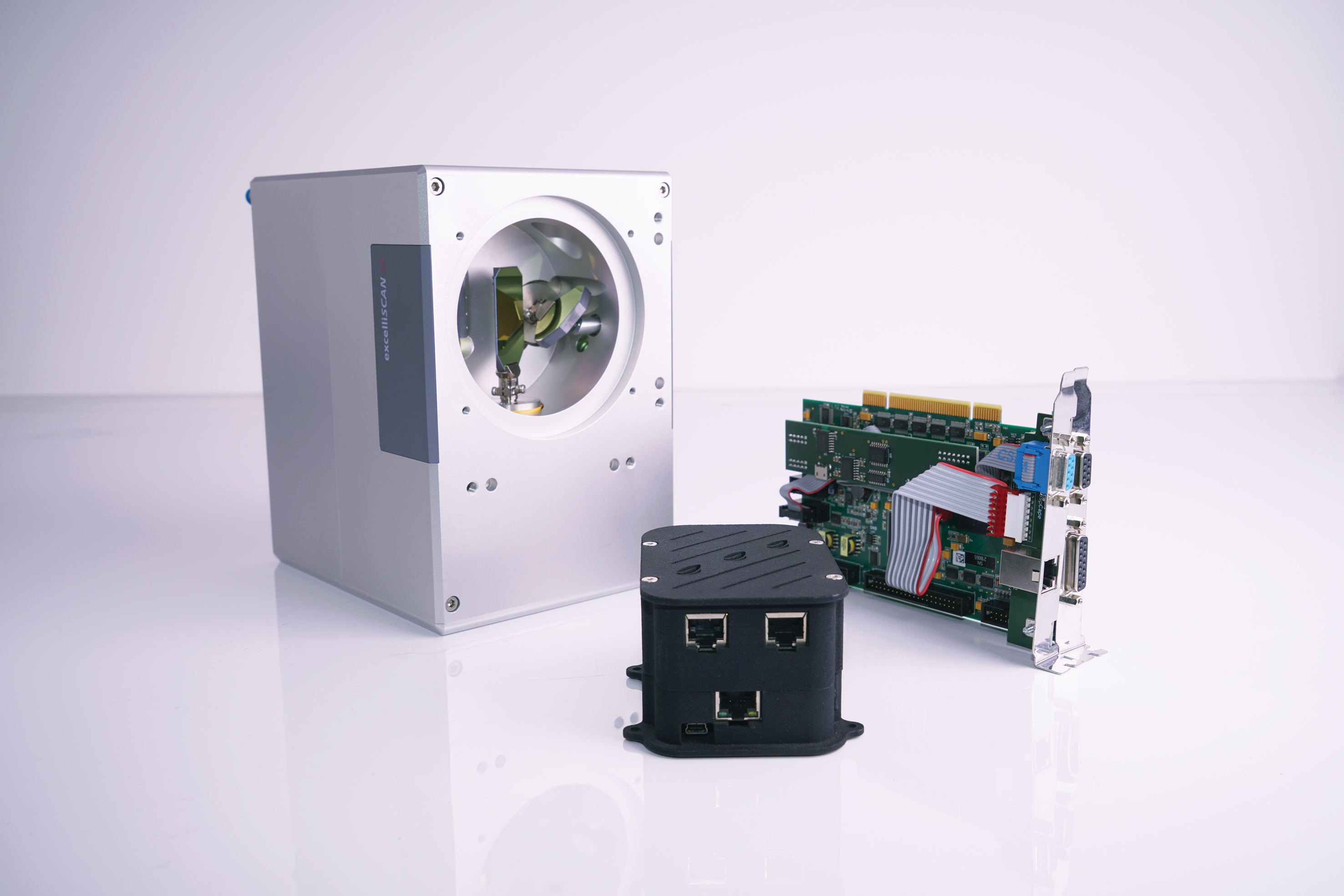
Control and Versatility The RTC4 series of control boards is available with two different interfaces: PCI Express (RTC4 PCIe) Ethernet (RTC4 Ethernet) These boards enable synchronous, real-time control of scan systems and lasers. Here you can download RTC software packages with the current drivers for your SCANLAB RTC control board. For RTC5 boards (PCI, PCI-Express) and RTC6 boards, the SCANLAB laserDESK software is available. LaserDESK lets you easily create and execute professional laser jobs. Please ask your sales contact, if you should need additional information.
RTC3/4/5/6 |
|---|
differential tracks: |
16-pin connector: Encoder X1+ |
16-pin connector: Encoder X1- |
16-pin connector: Encoder X2+ |
16-pin connector: Encoder X2- |
16-pin connector: Encoder Y1+ |
16-pin connector: Encoder Y1- |
16-pin connector: Encoder Y2+ |
16-pin connector: Encoder Y2- |
Table 38: Possible MOTF connection for RTC cards

To get to the dialog, choose Menu bar → Settings → System → Card → Advanced → Driver Settings for RTC3, RTC4, RTC5 or RTC6. Enable Marking On The Fly and then go to Settings.
Figure 296: MOTF Settings for RTC Cards
Encoder Kx/Ky: Distance in x/y direction per encoder count. Example of a RTC MOTF-Kx/Ky calculation. In this calculation the radius of the encoder wheel is 50 mm and the encoder is generating 2000 pulses per track (A and B) and full rotation:
External Trigger: Allows to define an offset between external trigger pulse and the start of the job process. The offset is defined by Delay and the unit is encoder steps.
| • | RTC3/4: Simulation must be Off. The Delay value is internally multiplied by 16 counts. |
Simulate Ext Start: Allows to repeat the job automatically. The gap between the jobs is defined by Delay and the unit is encoder steps.
| • | RTC3/4: Simulation must be Off. The Delay value is internally multiplied by 16 counts. |
| • | The TriggerMode (Mark → Trigger) must be used. |
| • | The initial job must be started with an external trigger signal on /START. |

| • | Depending on the direction of the belt, a positive or negative number must be entered. |
Simulation: Encoder pulses will be simulated with a constant pulse frequency of 1 MHz.
Off: No simulation

Encoder X: Simulation in X-direction

Download Scanlab Drivers

Download Scanlab Driver Win 10
Encoder Y: Simulation in Y-direction
Download Scanlab Driver Download
If the marking is started with an external trigger (sensor), it is recommended to start the marking in trigger mode (Mark →Trigger) to avoid jitter of the position. |


